
LINKS TO FEATURED PAGES:
![]() TRIUMPH
Contents page
> Weber DCOE technical information
TRIUMPH
Contents page
> Weber DCOE technical information
|
Weber DCOE carburetors and the Triumph TR2 through TR4A engine
This web page covers Weber DCOE carburetor theory of operation and tuning as it applies to the Triumph TR3 and TR4 engine. When I first installed a pair of Weber 45 DCOE carburetors in my TR3A, I knew very little about them so I started looking for information. I never found a single source that told me all I wanted to know about the Weber DCOE, nor one that went sufficiently into the use of DCOEs on the Triumph TR four cylinder engine. What follows is basically my collection of notes accumulated a bit here and a bit there from dozens of sources over several years. Edoardo Weber developed his first carburetors in the 1920's. What made and still makes his carburetors so appealing (other than their overpowering charisma) is the adaptability of his designs. Carburetor functions that are cast into the bodies of other carburetors are separate tunable parts in Webers. You can even change the size of the venturi itself. This means Webers can be tuned specifically to individual engines to work best with the cam, exhaust system and compression ratio of your particular engine. They can be tuned for excellent fuel mileage, maximum power or anyplace in-between. Most people who buy DCOEs intend to tune for maximum power and not maximum fuel economy. If you are tuning for maximum fuel economy stick with the low jet and venturi numbers that I discuss below. The problem with extreme adaptability is that it is a two edged sword . One edge allows you to closely tune the carburetor to your engine, the other edge leaves you wondering lost in a vast myriad of tuning component possibilities each affecting the function of the others. What I hope to do here is provide a tuning map of sorts, specifically for the TR2 through TR4A engine. Please take this as my best guess and current understanding and not as expert opinion or as the absolute truth. Beware of looking to other brand same displacement engines for clues about carb size and jetting. The TR engine is low revving and high torque. The engines that came from the factory with DCOEs tend to be low torque high revving engines. Their jetting and venturi size will be wrong for the TR engine.
Some engine backgroundThe engine used in the TR2 through 4A and most Morgans of the same years is a low revving torquey engine. There are major crank shaft harmonics around 5200, 5800 and 6200 RPM. The one at 5200 RPM tends to break the crank at the base of the flywheel mounting flange if you spend much time there. The one at 6200 is at the middle of the crank and tends to beat up the middle main bearing, Triumph factory race cars were red lined at 5000 RPM (same as a stock engine) so they would not break the crank on a long race. As far as I know, only UK built factory TR4 rally cars were built with Weber carburetors. Most of these rally cars got 42DCOE's because they were available cheap. A few UK rally cars evidently either got 45DCOEs or were upgraded to 45DOCEs during their racing careers. All the other factory race TR3 & 4's were fitted with SU's. There is a harmonic dampener kit currently available (Racetorations in the UK, British Frame & Engine in the US) that tames the 5200 RPM harmonic quite a bit and possibly the others as well. Nitriding the crank increases its hardness and is a must if you want to rev the engine. So are such things as balancing the engine, lightening the rocker assembly, going to an aluminum flywheel and going to stronger valve springs and retainers. Also be aware that current stock non asbestos clutch disk linings seem to come apart if you spend much time at or above 6000 RPM. First some DCOE tidbitsDCOE 40, 42, 45 and 48 all share the same basic construction. They all take the same jets, brass fittings and gasket set. The chokes, auxiliary chokes, horns, butterfly valves (throttle plates) and throttle shafts are unique to each carburetor size and are not interchangeable between sizes. The 40 and 42 share one choke and auxiliary choke design (they look the same even though the outside diameter is different) and the 45 and 48 share a common design. Visually it is easy to confuse these parts without a trial fit. 42DCOE 8 Webers were only used as the standard carburetor on the Maserati 3500 GT and the Morgan Super Sport. Maserati paid to have a bunch of 42DCOEs special built so they would be available for this one engine. Consequentially, during the late '60's and early '70's 42DCOE8s were widely available at deeply discounted prices from Weber. They were the cheap conversion of choice for Triumphs, Morgans, Ford Pinto and Capri 2000 (when dual DCOEs were used), Volvo 122S, 144, P1800. 42DCOEs have been out of production for several years as have their chokes, aux. chokes, butterfly valves and throttle shafts. 40DCOE throttle shafts are the same size except for the width of the slots for the butterfly valves. They can be filed wider and used on 42DCOEs. As far as I know Pierce Manifolds is the only company in the US that ties to keep 42 DCOE parts in stock. Choosing a DCOE sizeWhen the TR4 engine was fitted with DCOEs from the factory during the sixties (Morgan Super Sport and Triumph TR4 factory rally cars) and by individuals for racing, the carb most often used was a 42DCOE 8 because they were comparatively cheap. These carbs have been unavailable for a long time. So our choice for new carburetors. boils down to the smaller 40DCOE or larger 45DCOE. Which you pick will depend upon how the engine is built, how you intend to drive the car and what you wish the red line to be. As an aside, the prefix number on the DCOE is the diameter of the throttle plate (the throttle bore) in mm; DC means "doppio corpo" (double throat); O means "orizzontale (horizontal); E means it is a die cast carburetor; and the number or number and letter suffix is the variation type. Except there seems to be several variations to most variation suffixes. You want to be very sure that the DCOEs you purchase are indeed matched pairs with matching progression holes. You will never get two DCOEs to work together properly if they are different variations. The Weber choke is a removable venturi. The larger the choke (venturi), the more air fuel mixture can flow through it and the less flexible the engine will be at lower RPMs. The smaller the choke the better the low & mid end is and the sooner it will start restricting flow at higher RPMs. The ideal choke size is the minimum size that provides good flow at your maximum usable RPM. Going larger than that costs you low end a mid RPM power without increasing high end power. Here is an excerpt from an e-mail I received from Kas Kastner (12/9/03) on the subject of TR engine air flow through the intake.
Just a reminder that bigger is not always better. Here is what I have picked up as choke rules of thumb for the Triumph four cylinder engine. 36 mm choke - race engine or highly modified street engine with 87 or 89mm pistons, redline 6000 RPM or higher. High speed power is the most important but mid range power is also important. You want the engine to pull strongly through 6500 RPM. This would be a good size for most prepared race engines expected to be used on high speed circuits. 36 chokes may be an overkill on a hot street engine where 90+% of the time RPMs will be well below 6000. 38 chokes may be a possibility on all out track race engines. 34mm choke - modified street engine, auto cross, 86, 87mm pistons, "fast street" cam (260-280 degrees) or longer duration. Wide power curve possible with correct cam. Very slightly better low end power than 36 chokes but starts running out of breath much beyond 6200 RPM or a little higher depending upon cam and flow characteristics from air horn to tail pipe. Requires a nitrided crank and harmonic dampener to get the best from the carbs. This would be a good size for auto crossing, European style rally cars and other fast driving where there are tight curves and you have the need to accelerate quickly as well as run at high speeds. 32 mm choke - basically stock or mildly warmed up engine, This is where all but the most radical street driven TRs probably should be. 83 or 86mm pistons, stock or mild "street" cam, 5000 RPM red line (stock engine rev limit). Highway cruiser with lots of low speed flexibility. If you are using a stock crank and mechanical fan you need to retain the 5000 RPM readline which means a 32 mm choke is about as large as you will be able to make full use of. Can be tuned for good fuel economy and provides the best stop and go around town drivability. Smaller chokes down to 30 can be considered for stock engines being tuned for maximum economy and regular town and highway driving. Here is where you choose your DCOE. The largest choke that will work optimally in a 40DCOE is a 34 choke. The smallest choke that will work optimally in a 45DCOE is a 34 choke. While larger chokes are available for 40DCOEs and smaller ones are available for 45DCOEs they will not work as well for this application. The 42DCOE only had 28, 30, 32 and 34 chokes available. If you intend to keep the engine at or below 5000 RPM, the 40DCOE will provide you with your best all around power curve. This will handle fast street applications and 5000 max RPM auto crossing quite well and give you lots of low end flexibility. The 34 chokes will give you fast street and you can choke down for additional low end grunt or better fuel economy. As a comparison, the 2L Alfa Romeo engine was equipped with 40DCOEs and 32mm chokes from the factory for both power and economy. So this combination should provide adequate power and economy for a 2L ex-tractor engine. If you have a stock crank and no harmonic dampener keep the engine red line at 5000 RPM and stay with 40DCOE Webers. 45DOEs would be overkill and may not work quite as well in your application. If you want to rev higher, nitride the crank, go to a lighter flywheel and get the harmonic dampener kit. You only need 45 DCOEs if you are track racing or auto crossing at higher revs. The 36 chokes can provide a little extra with the wild cam and 12:1 or higher compression. 45 DCOEs with 34 chokes will work fine for high RPM fast street or auto cross but so should 40 DCOEs with 34 chokes. The rule of thumb seems to be to fit the smallest choke that will give you full power at your maximum usable RPM. The smaller choke will provide better overall flexibility and power. Going to a larger choke will allow you maximum power at peak RPMs but will reduce low end power. I'm currently running 34mm chokes in 45DCOEs on my TR3A engine. The engine pulls strongly past the point where the 6000 RPM tach is buried. The cam I'm using is designed to pull strongly between about 2500 RPM to 6000 RPM then have a wide flat top end. Make an honest evaluation of your engine and driving habits THEN choose the most likely correct choke size THEN choose the DCOE carburetor size that fits the choke THEN purchase your carbs as a matched pair from a reliable source. Do your homework first and order matched carbs equipped with your best guess of venturis and jets from a dealer that will set them up to your specifications. If your dealer is not willing to sell you a set of Webers custom assembled with your best guess jetting, walk away and find a dealer who will. Chokes and jets are expensive so you might as well start with a close ballpark set instead of paying for a bunch of parts you have no use for. Don't forget even hot street vehicles will be spending most of their time with the engine revving below 4000 RPM. Don't over carb an engine used 90% for the street. 1990's vintage Spanish origin Weber DCOE 45 152s manufactured in Spain during the 1990's have only three progression holes. This is not enough for smooth operation of the TR3/4 engine over the entire operating range. People put over rich idle jets on these carbs to compensate and keep the engine from stumbling between idle and when the main jets take over. The newer DCOE 45 152G carbs have five progression holes allowing you to obtain a smoother progression between idle and the main jets while keeping the air fuel mixture correct. If you are searching for new DCOEs look for the DCOE 45 152G. The are Weber specialist shops that can drill additional progression holes into the 1990's DCOEs if you find then for a very good price. Beware of the bargain used DCOE carburetors that someone decided not to use. They may end up costing as much or more than a new ball park jetted DCOE by the time you pay to replace wrong size venturis and jets. Weber chokes and auxiliary chokes do not come cheap. 45 & 48DCOE chokes:
40 & 42DCOE
Chokes
|
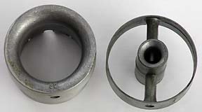
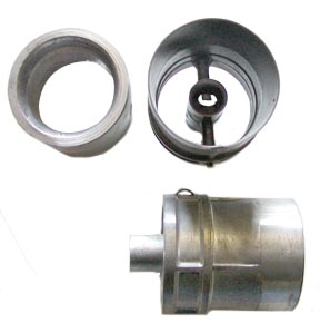 42DCOE choke & aux. choke |
40and 42 DCOE's share the same choke design. Their difference is their outer diameter. Venturi (choke) shown on left. The size number is stamped on the front where visible looking down the barrel. This one is a 32mm choke for a 42DCOE. Auxiliary venturi shown on right side. The size is stamped along the outer side next to the spring clip and is not readable unless the auxiliary venturi has been removed. The little centre venturi is where fuel from the main jet is drawn into the air flow. This is a 3.5 auxiliary venturi for a 42DCOE The auxiliary venturi extends from the venturi to the mouth of the carburetor. Note the spring clip on the side view. The clip keeps the auxiliary venturi from rotating. The air horn locks them into place. These carbs should never be used without an air horn. |
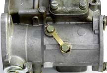
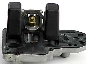
 42DCOE underside |
This is a picture of the underside of a 42DOCE which is the same as the 40DCOE. Note that there are no venturi mounting bolts on the underside. The venturi is held in place by the auxiliary venturi which in turn is held in place by a steel spring clip (see side view of aux choke above) and the air horn. The spring clip slides down a slot in the throat |
Auxiliary chokes
The auxiliary chokes are small suspended venturis that sit inside the throats of the DCOE and atomize fuel from the main cruise circuit into the air stream.
The number on the auxiliary choke refers to the diameter of the cross section area of the delivery port (venturi) and not the size of the fuel nozzle that delivers fuel into the port. The smaller the diameter, the higher the air velocity through this suspended venturi and the sooner the main or cruise circuit comes into play.
To understand the role of the auxiliary choke you need to understand how fuel is delivered to the engine at different RPMs. The DCOE has three different fuel delivery systems (not counting the cold start and accelerator pump circuits) that deliver fuel into the throats of the carburetor at different RPMs. Tuning a Weber is a matter of trying to obtain the relationship shown in the graph below.
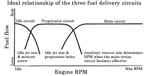
Ideally you want the richness level of each circuit to be the same. The ideal intersection of the curves is where the fuel delivery of the circuit going out plus the fuel delivery of the circuit coming on added together equals the total amount of fuel delivered when either circuit is in the middle of its range.
The idle and progression circuits are cast and drilled into the carburetor body making the location of their curves at fixed engine RPMs. The idle jet provides fuel to both the idle and progression circuits. This jet determines the richness of the progression circuit and the idle mixture adjustment screw sets the richness of the idle circuit curve. The main jet stack sets the richness of the main circuit and the size of the auxiliary venturi determines the RPM at which the main circuit curve intersects with the progression circuit curve. The main cruise circuit usually comes into play around 2800 to 3000 RPM. Below that, the engine is operating off the idle jets. This should help you trouble shooting any problem that occurs only above or below around 3000 RPM.
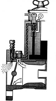 |
Here is how fuel is delivered to the cylinder. At idle the throttle plates (butterfly valves) are closed and fuel flows into the cylinder from an idle hole behind the throttle plates. As the throttle plates start to open, the top edge of the plates move towards the mouth of the carb and encounters a number of progression circuit holes. These holes provide additional fuel into the increasing air flow. As the edge of the throttle plate passes a progression hole, the vacuum behind the plate draws fuel out of that progression hole. The additional fuel added by each progression hole keeps the cylinder from burning too lean in the RPMs above idle and before the cruise circuit kicks in. If the initial adjustment of the throttle butterflies is open enough to uncover a progression hole, the engine will suck the fuel from the progression circuit during idle, resulting in a lean off-idle flat spot and poor fuel mileage. If the idle position of the butterflies is not set right you will never obtain a good consistent idle and smooth off idle transition. This is where most people go wrong setting up DCOEs. |
 |
 |
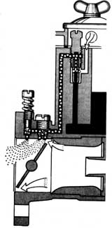
By the time the engine has passed about 2800 RPM, the top edge of the throttle plate has passed all the progression holes and is opening wide enough to cause the vacuum to drop to where it is drawing progressively less fuel out of the progression holes. This is when the main cruise circuit needs to start kicking in so that the increasing level of fuel delivered by the main jets supplement the decreasing level of fuel supplied by the progression holes. The size of the auxiliary choke determines when the main jets will start delivering fuel. If it kicks in too early (too small of a auxiliary choke) you get an over rich condition and the engine bogs or stumbles in the progression (or just wastes fuel with no noticeable symptoms). If the auxiliary choke is too large there can be a lean area where the progression openings are not delivering enough fuel and the main cruise circuit has not yet kicked in. This leanness is masked during acceleration by the accelerator pump. It would be seen as a leanness in a narrow RPM band while in a constant low RPM cruise (this is where an onboard CO monitor that can be read during driving would come in handy). The goal here is to fit the smallest auxiliary choke that will not cause an over rich bog or stumbling during a slow opening of the throttle plates. This will assure the absence of a lean RPM band that might damage the engine over time. Most DCOEs fitted to TR engines use 4.5 auxiliary venturis. They seem to work OK on the engines so no one seems to swap them out to see if other sizes would also work. HP books "Weber Carburetors" suggests 40DCOE, 32mm chokes and a 3.5 auxiliary venturi for a stock 2L TR engine. |
A Note About Jets
Most DCOE jets have tapered ends. The tapered end of these jets sit snugly against seats in the carb body to create seals between different areas of the carburetor. If the seal is not made or is broken the carburetor will not function properly.
These jets are mounted onto holders with a friction fit. As the holder is threaded in, the taper at the end of the jet comes into contact with the passage seat and is pushed back into the holder maintaining a contact seal. If the jet is initially pushed all the way into the holder it may not reach all the way to the passage seat. The fit between the jet and holder should always be tight. A loose fit can allow a jet to back away from the seat over time.
The proper method of installing a jet is to fit it only about one eighth an inch into the holder then allow the passage seat to push the jet in the correct distance as you screw in the holder. Be careful not over tighten the jet assemblies. Once the jet is seated it doesn't take much torque to hold everything in place.
Most jet sizes are in numbers that give their actual diameter in hundredths of a millimeter. Idle jets can also have F numbers that indicate their ability to emulsify fuel. The number behind the F has nothing to do with the hole flow rate. Emulsion tube designation is by the numerical order in which they were designed and has nothing to do with their flow characteristics. There is NO flow relationship between different number designations of emulsion tubes.
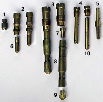 |
1. Intake and discharge valve for accelerator circuit 2. Idle jet assembly 3. Main jet stack 4. Starter jet assembly 5. Accelerator pump jet 6. Idle jet 7. Air Correction jet 8. Emulsion tube 9. Main jet 10. Start jet (Cold start circuit) |
Idle Jets 
Idle jets affect the idle and progression circuits of the DCOE. They are selected primarily for proper running of the progression circuit which extends from just above idle to where the main jet assembly takes over (somewhere around 25-2800 RPM). Proper selection is critical for smooth, economical low RPM cruising.
At idle, the fuel is mixed into the airflow behind the throttle plate (butterfly valve) and the flow is regulated by the idle flow screw. There are a series of progression holes, not affected by the idle screw, that get exposed behind the throttle plates as the throttle continues to open. As the throttle plate top edge moves past each hole, the vacuum behind the plate draws fuel from the idle jet out through that progression hole. This adds progressively more and more fuel to keep the engine running smoothly off idle until the airflow is high enough to draw fuel from the main jet. Since the progression holes are not adjustable, the idle jet is chosen primarily for the progression circuit.
Idle jets have a fuel hole drilled in the bottom of the jet and an air bleed hole drilled in the side.
The fuel hole regulates the amount of fuel for idle and gradual progression from the idle circuit to the main cruise circuit. The goal is the smallest hole that will provide a good smooth progression.
The air bleed hole affects the air fuel ratio of the fuel in the idle and progression circuits. A small air bleed hole means a richer mixture ratio and enlarging the hole leans out the air fuel mixture.
The larger the choke the richer the idle jet needs to be because the main system comes in at higher rpm as the choke size goes up.
Here is the complete list of idle jet air bleed holes in order from rich to lean
F6 (richest), F12, F9, F8, F11, F13, F2, F4, F5, F7, F1, F3 (leanest)
Best choices for the TR engine is 45, 50 or 55 jet with F9 or F8 air holes. 50F9 is always a good ballpark jet size for these engines with 86 or 87mm pistons. The goal is to end up with the leanest mixture that provides correct performance through the progression circuits.
Before setting up the idle
It is important to be very sure there is no throttle shaft bind or over tightened levers. Of course this can best be checked for before the carbs are mounted. Open then close the throttle slowly. Then give the lever a little extra push in the closed direction. If the throttle shaft is binding it will not return to fully closed if you let the internal throttle springs close it gently. An accidental drop that strikes the throttle linkage can cause the shaft to bend just a little so that it binds. Test before you buy.
After mounting, linkage going to a common throttle bar should be identical in length and you should carefully check to make sure that the throttles of all carbs are completely closed when the linkage is is the closed position. Test the complete throttle linkage for any tendency to bind and not return the throttle plates to the fully closed position. Backup external throttle springs should be considered an important safety feature. Sync the carbs before setting the final idle. When balancing multiple carbs be sure to bring the high carb(s) down to the low carb, then bring them both up to proper idle speed.
Setting up the idle
Where just about everyone goes wrong setting up DCOEs is to use the idle lever adjustment screw to adjust idle RPM. More often than not this ends up uncovering the first progression hole at idle. This will cause you to pick the wrong idle jet, or if you have the correct one there will be a lean flat spot right off idle that you will be unable to compensate for.
First you adjust the idle jets for smooth idle then you set the idle speed if needed. If the engine does not get enough air to idle on its own with the throttle plates closed, you need to adjust the idle RPM before setting up the idle jets.
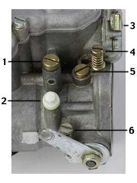 |
Illustration key: To set the butterfly valves correctly, adjust the throttle plate screw (6) to where it just touches but does not move the throttle shaft. Turn the screw in 1/2 turn then do not touch this screw again. This screw is not intended to be used to adjust idle speed. If there is enough air flow the idle RPM will be correct after properly setting the idle adjustment screw (4). If there is not enough air flow, the idle RPM needs to be adjusted after the idle mixture is set. Next, set the idle mixture adjustment screws (4) to one turn off closed and start the engine. First, turn the mixture screw towards closed in 1/4 turn increments until the engine dies or runs worse, then back out the screw in 1/4 turn increments until the screw does nothing or the engine runs worse. Then turn the screw back towards closed until you reach the point where the engine just starts to run poorly. Once there, turn the mixture screw back out to the leanest point where you encounter the best, fastest and smoothest idling. Use your ear, not a scope or tuning instruments for this. You want to tune the idle mixture by sound and feel. |
If the idle jet size is close to correct, the best idle point should be when the idle mixture flow screws (4) are between 7/8 of a turn to 1-1/2 turns off closed. If only a half turn or so of the idle flow screw from closed obtains the correct idle RPM chances are the fuel opening in the idle jet is too large and you should try the next leaner jet. If the screws need to be turned out 1-1/2 turns or more chances are the the fuel hole in the idle jet is too small and you should try the next richer jet.
If you are taking a CO reading, 2.5% CO at idle is ideal for a street engine. Higher than 3.5% is unusable and just provides poor fuel consumption without gains.
If you can not obtain a correct idle by adjusting the idle mixture screw then the throttle plates are not passing enough air and you need to increase the amount of air going past the throttle plates.
On newer DCOEs with Venturi balance adjustment screw (2):
The venturi balance circuit is an air path that bypasses the throttle plate. The amount of air that bypasses the plates is controlled by the adjustment screw. What this does is allow additional air to go past the throttle plate at the idle position when the throttle plate does not pass enough air for the engine to idle properly (remember we do not adjust the idle adjust screw (6) after it is set at 1/2 turn). Adjusted properly it will let enough air past the throttle plates to allow the engine to idle properly. This adjustment is very sensitive so a little amount of turn can make a big difference in idle.If the engine will not idle with the throttle plates closed set the idle lever adjustment screw (6) to 1/2 turn beyond initial contact, the idle adjustment screws (4) set at one turn up from fully seated. If the carbs idle and both Venturi balance adjustment screws fully seated. adjust the Venturi balance adjustment screws 1/16th turn off seated then start the engine to see if it idles. If not, adjust both Venturi balance adjustment screws out in 1/16th turn increments until a ballpark idle is achieved then zero in the idle using the idle mixture adjustment screws. When you are satisfied that the Venturi balance adjustment screws are correct, tighten down on the lock nuts and put the cover over the adjustments as they should never need to be adjusted again.
On older DCOEs without Venturi balance adjustment screw (2):
The throttle valves need to be modified to allow additional air flow in the idle position. This is done by drilling holes in the throttle plate near the bottom edge. Drill a 1/2 mm dia hole in each plate on each carb, refit the carbs then try to get the engine to idle. If there is not enough air flow, enlarge the holes to 1mm and try again. If you still do not have enough air, drill a second 1/2mm hole near the first, refit the carbs and try again. Some people file the bottom of the throttle plates to get extra air flow. I do not recommend this as there is no way to assure you have filed the exact same amount off each throttle plate on each carb.
The final selection for idle jets should be based upon how the engine performs in the progression circuit over the progression band.
Before making the final testing for the idle jets make very sure the ignition is properly set up and functioning with the advance not starting until around 1200 RPM and properly advanced initial timing. With a modified engine the initial timing will probably be in the neighborhood of 8 to 12 degrees BTDC with at total advance of 32 to 34 degrees. An ignition timing problem can be seen as a progression circuit leanness. Initial timing that is too retarded for the engine is a source of spitting out through the carburetor throats.
Slowly advance the throttle off idle and listen for any hesitation. If there is a hesitation the mixture is too weak. Adjust the idle flow screws out 1/2 turn and try again. If the hesitation is still there the jetting will need to be altered. On a TR engine if a F8 air bleed hole is too lean try an F9. If you are too lean with an F9 go up a jet size with an F8 air bleed hole. For other engines, try two steps richer on the air correction hole while leaving the fuel hole the same size. Reset the idle then retest. For non TR3-4 engines, if going to the richest level (F6) does not get rid of the hesitation, go to the next size larger fuel hole and rerun the tests with different air bleed holes.
When the no load tests are completed drive the car and retest under load conditions.
The ideal idle jet size provides an idle CO in the 2.5 to 3% range with the idle flow screws adjusted between 7/8ths of a turn and 1-1/2 turn and does not cause the engine to hesitate on the progression circuit. The next leaner air bleed size would cause a hesitation under load conditions. A richer jet will provide poorer fuel consumption. An over rich jet will not provide top performance.
If you have the throttle linkage connected at this time, the rods between the carburetor's throttle arm and the crank need to be identical in length. Different length arms will affect the carburetor synchronization as you move off idle.
Main jet/emulsion tube/air correction
jet assembly 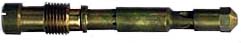
These three items form the main jet assembly that provides fuel to the engine once the throttle plates (butterfly valves) are open beyond the progression holes. The emulsion tube is a long brass tube with openings along the side. The main jet is a friction fit into the bottom of the emulsion tube. The air correction jet is a friction fit into the top of the emulsion tube.
There is a fuel passage that goes from the float chamber, through the main jet and into the emulsion tube. When the engine is not running the fuel level inside the emulsion tube is the height of the level in the float chamber.
There is an air passage from the small hole on the face of the DCOE into the float chamber, through the air correction jet and into the emulsion tube.
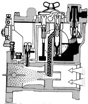
As the throttle plates move towards full open they cease to draw enough vacuum to pull fuel from the progression holes and start drawing fuel from the auxiliary chokes.
The vacuum at the auxiliary choke draws an emulsified air fuel mixture from the emulsion tube and out through the auxiliary venturis. As the emulsified air fuel mixture is drawn out of the emulsion tube, fuel flows from the float chamber through the main fuel jet into the emulsion tube to replace the emulsified air fuel mixture being drawn out of the emulsion tube.
Air is also drawn down through the air correction jet into the emulsion tube where the air and fuel are mixed.
Choosing the correct stack is essential for cruise and high RPM performance.
Main jets 
The main jet controls the fuel mixture in the emulsion tube in the mid RPM range when the cruise circuit is activated. As the RPM range increases the air correction jet becomes more of a factor and becomes the dominant partner in controlling the mixture at high RPMs.
The main jets are numbered by the diameter of the jet opening and come in size steps of 5 hundredths of a mm. Too lean a jet can damage the engine through overheating. Too rich a jet washes the oil off the sides of the cylinder walls and causes rapid cylinder wall wear.
The ball park rule of thumb for picking a jet main jet size for a street engine operating at sea level is to multiply the venturi size times 4. The common main jet range for the TR engine operated near sea level is 135 for stock engines and normal street driving through about 150 for high performance race cars. 140 and 145 seem to be the most common sizes for high performance street and auto cross
At high elevations our engines are getting less air, so they need less fuel to maintain the proper air/fuel ratio. Generally you would go down 1 main jet size for every 1750 to 2000 feet of elevation you go up. If you normally run a 140 main jet at sea level you would drop down to a 130 at 4000 feet. Something else goes down as you go up in elevation is horsepower. You can figure on losing about 3% or your power for every 1000 feet you go up. At 4000 feet your power will be down about 12%-even though you re-jetted!
Air correction jets 
The air correction jets only affect the top end performance of the engine. The larger the number on the jet the larger the air hole and the leaner the main jet runs at higher RPM.
If the air correction jet is too lean (too large a hole) the engine will miss near peak RPM. If the air correction jet is too rich (too small a hole), the engine will not produce optimum power. For testing purposes, find the largest diameter air correction jet that causes a high RPM misfire then fit a 10 to 20 smaller dia (richer) air correction jet.
The air correction jet number is their hole diameter in hundredths of a millimeter. and range in size increments of 5. When testing, the minimum increment of changes should be at least 10 with 20 being the more common increment to notice changes.
Here is a guideline for approximate air correction jet selection for those of us without a large supply of air correction jets:
For stock to mild engines with a 5000 RPM redline where fuel economy is a strong factor, a good starting point for the air correction jet is figured by adding 50 to your main jet size.
As you progress towards a full race engine and higher RPMs the size of the air correction jets decreases (fuel mixture becomes richer), with a full race TR engine having an air correction jet size of about 10 or 20 hundredths of a millimeter. larger than the main jet size.
For a modified street engine running 34mm chokes having a red line at or below 5000 RPM, adding 30 to 50 to the main jet size would probably be a good starting point for the air correction jet.
For a modified street engine running 34mm chokes and having a red line around 6000 RPM, adding 25 to 40 to the main jet size would probably be a good starting point for the air correction jet.
For a modified engine needing 36mm chokes to produce full power above 6000 RPM adding 10 or 20 to the main jet size will probably be a close starting point.
Emulsion tubes 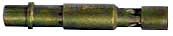
As the name implies the emulsion tube is where air is mixed with fuel to form an air/fuel emulsion (fuel with lots of little air bubbles in suspension). The vacuum formed in the auxiliary choke draws this emulsion out of the emulsion tube and into the air streaming through the auxiliary choke where it is atomized into the air stream and delivered into the combustion chamber.
The emulsion tube affects the acceleration phase as the main jets are activated. If the emulsion tube size is incorrect the engine will not accelerate cleanly when the main cruise circuit is operating. The effect of changing emulsion tubes can be very subtle to detect. Emulsion tube operation is very sensitive to the fuel level in the float chamber. So you need the right size float valves and closely set floats for the emulsion tubes to work as intended.
Emulsion tubes differ by their internal diameters and the number, size and positions of the side holes. They are complex tubes where "just the right level of emulsification happens here". Their part number reflects the order in which they were developed and not any physical attribute.
The tube sizes are (in order of rich to lean):
F7 (rich), F8, F2, F11, F16, F15, F9 (lean). There are additional sizes.
F15 emulsion tubes seem to be the size universally recommended for Triumph TR engines and they seem to work OK. I do not understand them enough to experiment since so much of what happens is determined by the air and main jet sizes and the level of the fuel in the float chamber while the engine is running.
Accelerator Pump Jet 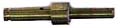
The accelerator circuit consists of:
- A fuel reservoir,
- A mechanically activated, spring loaded plunger (pump) that
flushes the reservoir,
- A one way valve that lets fuel into the reservoir from the
float chamber but not back out to the float chamber while the
plunger is purging the reservoir (called an Accelerator pump
intake/discharge valve),
- And an accelerator pump jet that both meters the amount of fuel pumped by the acceleration pump (plunger) and delivers that fuel directly into the rear of the carburetor throats.
The metering hole in the accelerator pump jet has to be large enough to remove any hesitation or stumble caused by the lean condition created by suddenly opening the throttle plates (butterfly valves) at low RPM. Too large a jet will cause a "bogging down" of the engine from too much raw fuel.
The jets are numbered for their hole size in hundredths of a millimeter. and are in five hundredths of a millimeter. steps (i.e. 35, 40, 45, 50).
Accelerator pump jets commonly recommended for the TR four cylinder engine are 40 and 45. Use the smallest jet size that will eliminate any hesitation or stalling when the throttle is suddenly opened.
The accelerator pump intake/discharge valve can have a discharge hole that finely tunes the flow of the accelerator pump jet in-between the step increments.
Accelerator pump intake/discharge
valve 
This is a one way valve that allows fuel to flow into the accelerator pump reservoir and keeps the fuel from going the wrong way when the accelerator pump is activated.
It can also be used to precisely tune the amount of fuel injected into the engine by the accelerator pump jet . This is accomplished by selecting a valve with a discharge hole on the side. If there is no discharge hole, the accelerator pump intake valve acts purely as a one way valve. If there is a hole, part of the fuel is discharged out the side hole back into the float chamber when the pump is activated, bleeding off the excess fuel not required to accelerate the car cleanly.
The number on a valve with a discharge hole is the size of the hole in hundredths of a millimeter., i.e. a valve marked 50 has a 0.5mm discharge hole in the side.
The most common accelerator pump intake/discharge valve size recommended for the TR engine is 50.
Needle valve
 |
The needle or float valve assembly regulates the amount of fuel allowed into the carburetor's float chamber and maintains the fuel level within a very limited range. The top stop of the float regulates the level of the fuel while the lower open stop regulates how far open the valve can open. The diameter of the valve regulates the rate at which fuel that can enter the chamber as the valve opens. There are a range of needle valve sizes available for the DCOE. The needle valve needs to be large enough to allow an adequate flow of fuel into the float chamber but should not be larger than necessary. Too large a valve will let too much fuel in quickly before it closes and cause a pulsing over rich condition. A 2.00 needle and seat is usually recommended for TR engines. A 1.50 needle and seat might work better on a TR engine with 83mm pistons tuned for economy but the 2.00 is always a safe bet. |
Some choke/jetting starting points based on the above:
Note these are ball park numbers based upon the recommendations of several people/companies/books/articles and should not be considered as absolute correct settings. During the time these recommendations were made pump gas was 100% gas. Since then Ethanol as been added to almost all pump fuels. Sometimes at a ratio of 10% or more. Ethanol is not as efficient as gas and you need more of an ethanol/gas blend than you do pure gas. But you need to begin somewhere. Just realize that the listed jetting will probably be ballpark for 100% gas racing fuels but will need to be larger for gas/ethanol blends. How much larger depends upon the blend ratio. From here run CO testing for the main jet/emulsion tube/air correction jet stack. The whole purpose for all these jets and air correction tubes is to be able to dial in your carburetors to closely meet the needs of your engine and your driving conditions. If you settle for a loose approximation you might as well have stayed with your original SUs or Strombergs.
Note: the 42DCOE settings on the chart are those published in most books but may not represent the optimum sizes for the application. Triumph UK racing department only used DCOEs on a small number of rally cars for a short period of time. They likely did not take the time to dial the carbs in for all driving conditions. I added that column because it is in all the books (likely all copied form one source) and people who are comparing this chart to a book are likely to feel more comfortable seeing it included. It is not there as a recommendation for jetting.
| Engine |
Economy |
stock |
modified |
modified |
modified |
Currently on |
Factory |
Tony Drews |
Greg Solow |
|---|---|---|---|---|---|---|---|---|---|
| choke |
30-32 |
32-33 |
32-34 |
34-36 |
36-38 |
34 |
32 |
36 |
40 |
| aux choke |
3.5 |
4.0 |
4.0-4.5 |
4.5 |
4.5 |
4.5 |
4.5 |
|
5.0 |
| idle jet |
45F9 |
45F9 - 50F9 |
45F9 - 50F9 |
50F9-55F9 |
50F9-55F9 |
50F9 |
50F2 |
|
55F6 |
| main jet |
130 |
130-135 |
130-140 |
140-145 |
145 |
145 |
140 |
135 |
145 |
| air correction jet |
190 |
190 -180 |
180-160 |
170 - 150 |
170-150 |
170 |
150 |
135 |
140 |
| emulsion tube |
F15 |
F15 |
F15 |
F15 |
F15 |
F15 |
F15 |
F16 |
F11 |
| accelerator pump jet |
40 |
40 |
40-45 |
45 |
45 |
45 |
50 |
|
35 |
| accelerator pump intake/ |
50 |
50 |
50 |
50 |
50 |
50 |
50 |
|
|
| Needle valve |
1.50 - 2.00 |
2.00 |
2.00 |
2.00 |
2.00 |
2.00 |
2.00 |
|
|
Float setting
The floats open and close the float valve. The closed setting regulates the fuel level in the float chamber and in the emulsion tubes.
Traditionally DCOEs came with soldered brass floats. Lately most if not all are being provided with plastic floats. The float settings are different between metal and plastic floats. Note: some of the additives in newer fuels may attack the plastic floats. If you start having problems that might be caused by incorrect bowl fuel levels and you have plastic floats it would be good idea to remove the top cover and inspect the floats.
The float setting is dependent upon the carburetor you use. Here is a chart for brass floats (My carbs have brass floats):
| DCOE series |
float valve closed |
float valve max open |
|---|---|---|
40DCOE, series 2, 4, 18, 22/23, 24, 27, 28, 31,32 |
8.5 |
15 |
40DCOE series 29/30 |
5.0 |
11.5 |
40DCOE series 44/45 |
7.0 |
14 |
40DCOE series 72/73, 76/77, 80/81 |
7.5 |
14 |
42 DCOE series 8 |
5.0 |
13.5 |
45DCOE series 14, 14/18, 17 |
8.5 |
15 |
45DCOE series series 9 |
5.0 |
13.5 |
45DCOE series 72/73, 76/77, 80/81 |
7.5 |
14 |
45DCOE series 38/39, 62/63, 68/69 |
5.0 |
14 |
Both floats need to have the identical setting. You may need to bend the arms between the two floats to get them exactly the same closed height.
The ideal tool to set the closed float position is a round rod with the precise diameter of the closed float setting. The seam of the float should not be taken into account when measuring the float level so there should be groves cut into the rod to clear the float seams. This will allow you to see both the accuracy of the setting and any variation between the two floats.
The open and closed measurements should be taken with the top gasket in place. The closed position should be measured just as the floats close the valve and not with the entire weight of the floats upon the valve. This is done with the top plate tilted a little over vertical.
Fuel pressure/ filtering
Webers need a pump that can provide a high volume of fuel at a low pressure. The fuel pressure should be regulated to between 1.5 and 2.5 pounds per square inch at high RPM and no higher than 3 PSI at low RPMs. Too high a fuel pressure will force fuel past the float valve causing rich erratic running.
Luckily for us the the stock AC fuel pump that comes on our engines pump in this range when healthy. A fuel pressure regulator is optional with the stock TR fuel pump. If you fit an electric fuel pump you will need to fit a fuel pressure regulator. If you use an after-market electrical fuel pump be sure to test the output pressure over a range of RPMs to determine if you need to fit a pressure regulator.
It is important that your pump supply at least 1.5 pounds pressure at high RPMs. If it does not it will require rebuilding or replacing. The key is enough volume to keep the fuel bowl full and pressure low enough as not to force the fuel bowl overfull.
Webers have a wire screen filter in the inlet. This filter does not have a good reputation for working well over time. Considering the size of some of the jet openings I suspect the built in screen is not really fine enough to prevent clogging. You should consider installing a high volume fuel filter between the fuel pump and the fuel regulator. On a street car it is s good idea to remove and inspect the screens as part of your 3000 mile service. New blends of fuel can cause some fuel lines to deteriorate along the inside. Your fist sign of this happening to you will be black particles on the screens. If you start to see black particles on the Weber's fuel screens it is time to replace all rubber fuel lines on the vehicle and clean the fuel pump's sediment bowl (Use a new rubber seal).
A word about fuel lines - Do not use regular worm gear hose clamps with steel braided fuel lines. The steel braided fuel lines are designed not to crush. You will end up with an iffy seal.
Mounting
DCOEs prefer to be mounted with a 5 degree upward angle and should never be mounted at a greater angle that 7 degrees above horizontal. They will not perform properly at a greater angle.
A new intake manifold should be checked for proper alignment. Preferably before you pay for it. If the studs are out of alignment the carbs will be out of alignment causing differences in the way linkage opens each carb and sync problems at some part of the throttle travel.
One thing you can check in the store is that the studs are at right angles to the carb mounting surface. Also if you have a DCOE handy you can slide it over the studs and assure yourself that the carb base will sit flatly on the manifold with no gaps.
It is harder to check TR four cylinder intake manifolds for stud alignment because you need two manifolds per engine. You need to test fit the manifolds to a head for alignment testing. Once fitted, lay a straight edge over each row of studs and look for an out of alignment stud. The recommended maximum of allowable misalignment is 0.25 mm (0.010 inches). If it is more than that you need to weld the hole shut, resurface the top, and align drill a new stud hole. Like I said, it is best to make this measurement before money changes hands or when you can return the manifolds for replacement or credit.
The top studs should protrude 38 mm (1.5 inches) from the manifold. The bottoms ones can be between 38 and 40 mm (1.57 inches).
DCOEs are susceptible to fuel frothing and should be installed with anti vibration mounts. There are a couple of kinds and each comes with instructions for proper tightening. If you use the kind with 'O' rings that sit in a groove be sure the 'O' ring doesn't slip when you are mounting them. That would guarantee an air leak in a venturi.
TR linkage uses a solid cross bar with an arm and push rod for each carb plus one for the pedal linkage. It is critical that each of the arms connecting the carburetors be exactly the same length (within 0.5 mm or 0.020 inches of each other). If they are different lengths the carbs will go out of synchronization as the throttle opens.
Here are drawings showing how TWM linkage is set up for dual DCOEs on TR engines:
The DCOE comes with a built in return spring. For safety, it is a good idea to add another return spring for each carb what will work if the linkage slips. This will be required if you go racing. MGB return springs work well for this application.
The DCOEs full of fuel are weights sitting at the end of the intake manifold. Manifolds have been known to stress crack over time and vibration. Some racers add a plate between the two carbs and a down diagonal brace from the plate arm to an anchor point connected to an oil pan mounting bolt. The brace rod is usually connected to it's anchor point at each end with rubber gaskets to reduce vibration. This relieves the weight off the manifold head studs and keeps stress cracks from appearing.
On a TR four cylinder engine the carbs sit above the exhaust headers. Most racers construct a heat shield that fits between the carbs and the headers to allow the carbs to run cooler.
Air horns and air filters
Air is not good at making sharp right turns and turbulence is built up at the sharp edges of a DCOE throat that does not have an air horn. This decreases the amount of air fuel mixture that can be delivered to the engine and disrupts the air flow within the throats. The air horns provide a smooth flow of air into the throats of the DCOE. The rounded edges of the air horn allow air to enter with a minimum of turbulence.
Air horns of some length should always be fitted to a DCOE if the carburetor is to perform correctly and provide the most air fuel mixture to the engine. The DCOE 40 and 42 carburetor requires air horns to lock the auxiliary venturis in place.
The distance between the intake of a cylinder and the beginning edge of the air horn is called "the run". As a rule of thumb, the shorter the run, the more top end power. The longer the run the more low end torque and low end throttle response is available. The length of the run is tunable by the length of the air horn. This is why there are a number of lengths available.
Of course with our low rev engines, a long run is desirable for maximum power within our usable power band. Unfortunately for us the inner wheel well limits the space for a long run (long air horns). This is especially true in TR3s where the front DCOE throat sits close to the inner wing.
Some TR3 owners modify their inner wings to provide additional space for the air horns and air filter. I personally decided to sacrifice a little performance and maintain a stock inner wing. I went with the shortest of the air horns which is basically just a rounded lip to minimize turbulence and a very short itg air filter that allows air flow through the side facing the carb openings. Even then I needed to modify the front lower edge of the itg filter for clearance.
Which gets me around to air filters. While the air horns on a DCOE look very good and "racy" they should be covered up by an air filter. Your expensive engine will not last all that long without an air filter.
Sock type air filters should be avoided because they create turbulence that keeps the air horns from working properly and lowers the overall air flow into the throats of the carburetors. The worst you can do is a right angle air horn with a sock.
In general air filters seem to fit into two types. One has a short tubular type element with solid ends and the other has elements on all sides except the back plate.
The type with the short tubular element tend to be very good but take up a lot of space. For proper air flow into the air horns there should be minimum of two inches of space between the end blanking plate and the openings of the air horns.
The type that has filter elements everywhere except the back plate can be considerably closer to the air horn because air flows in from in front of the air horn.
These filters almost all have oiled foam elements. There are some very good ones and some very cheap not good ones. Stay away from the cheap filters that only have a single layer of one size foam.
Also, foam filters rely heavily upon their sticky oil coating to filter properly. Follow the care instructions that come with your filter religiously.
K&N and itg are two good names in the foam air filter business. I personally choose an itg filter for my TR3. It allowed me to use a single air filter that fits into the tight clearance between the TR3 inner wing and the front venturi. With the front foam surface and very short horns I can get reasonable breathing on that front venturi. If you decide upon an itg filter the TR2-4A engine takes the itg 28-JC-50 backplate. Which filter you need depends upon the space you have and the length of your air horns. A TR4 has a lot more space for a filter than a TR3 has. A TR4 can take a flat top type but the TR3 with unmodified wing needs the half round type. Best to talk to a dealer for the correct filter for your TR.
itg has a formula (for their filters only) that calculates the minimum distance between the horn opening and the facing element for no negative affect in air flow. The minimum distance is calculated by dividing the inner diameter of the air horn by four. For instance the minimum non interference distance the filter face can be from a 58mm dia. air horn is 14.5mm (about 9/16s of an inch).
The shortest carb face to facing element filter itg offers for duel DCOEs is 55 mm. I used this height filter with a rounded top in conjunction with the shortest air horns available to achieve a fit adjacent to an unmodified TR3A inner wing
There is an air hole in the intake side of the carburetor above the throats that provides air to the float chamber and the various air bleed jets. It should not be blocked by the air filter backing plate and it should have the same pressure as the air horns get if you decide to build ram flow air box of some kind.
Timing considerations
If you just add DCOEs to an engine and start it up chances are that it will idle poorly and occasionally spit out the front of the carbs. Modified engines and engines with DCOEs need more than stock advance. Stock advance is 4 degrees BTDC. You will probably need at least 8 degrees BTDC initial timing with a cam and DCOEs. With a cam a good idle speed should be 800-1200 RPM depending upon the duration of the cam. If the timing is too retarded the engine will not perform well below 3000-ish RPM unless you had very big idle jets. A way too rich idle jet can mask a lack of spark advance and reduce carb spittings but will drastically decrease fuel mileage.
Maximum total advance (initial advance + vacuum advance + mechanical advance) on the TR engine should be 32 to 34 degrees. Too much advance causes the engine to run weaker at high RPMs and leads to early engine damage. I think max advance on a stock TR engine is 32 degrees. You should not use a vacuum advance with DCOEs. Distributor advance should be mechanical only.
The stock TR distributor would require experimenting with weaker springs on mechanical advance and some kind of block to limit the max advance. A precision adjustment is almost impossible.
Best bet is to purchase a Mallory mechanical advance distributor and a curve adjustment kit. The off the shelf Mallory distributor comes with a 28 degree curve which provides correct total timing when the distributor is set to the factory stock initial advance (stock cam). Depending upon your cam you will probably want to adjust the distributor's advance to 22 to 26 degrees then set the initial timing for total advance to 32 to 34 degrees.
A visual guide
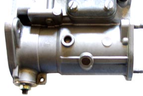
|
1. Cap for accelerator pump jet 2. Venturi balance adjustment with plastic cap. Fitted to newer DCOEs Screws should be seated unless needed to set proper idle 3. Cold start lever (choke) 4. Idle mixture adjustment screw. Used to adjust idle speed and to sync carbs 5. Progression hole cap. Allows access to progression holes for easy cleaning. 6. Idle lever adjustment screw. Set 1/2 turn past initial contact with throttle shaft |
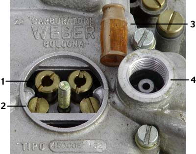 |
Top of a DCOE with centre cover and fuel filter cover removed 1. Main jet stack 2. Idle jet 3. Fuel filter screen 4. Fuel chamber for filter Notice how easy it is to get at the main and idle jets for cleaning or replacing. You can perform minor carb rebuilds without removing the carb from the manifold. |
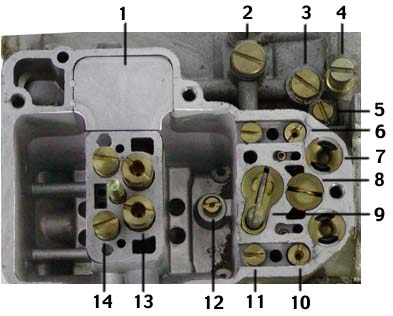 |
Top cover removed from a 45DCOE 1. Baffle plate (reduces chance of fuel sloshing up into air correction jets) 2. Cover for accelerator pump jet 3. Cover for progression holes 4. Idle adjustment needle 5. Second progression hole cover. Only on some carbs. 6. & 10. Start jet (Cold start) 7. Cold start valve assembly 8. Anchor plate for internal throttle return spring 9. Accelerator pump 11. Threaded plug Underneath is a check valve ball and a stuffing ball. 12. Accelerator pump intake and discharge valve 13. Main jet stack 14. Idle jet stack |
If you look into the bottom of the float chamber, on either side of the body
casting that holds the main and idle jets you will see two largish holes
going down. There is a baffled inner chamber area inside the casting that
feeds the jets. This baffling arrangement minimizes sloshing and helps keep
the fluid level constant under acceleration or cornering. There is an access
plate under the carb that allows you access to the inner baffle chamber.
for cleaning. Always use a new gasket.
Weber Tools
You can perform a minor rebuild on a DCOE without removing it from the intake manifold or disrupting the linkage. All you normally need is a flat blade screwdriver, pair of pliers, 10 and 12MM wrenches, a pin to poke through progression holes and a compressed air supply to blow out passages. Major rebuilds can require special Weber tools. If you are going to remove the throttle shaft the official Weber tool would come in most handy. A major rebuild that requires special tools is not for the weak of heart and may best be done by a Weber rebuild professional (Besides most special Weber tools are expensive). I broke down and purchased my first Official Weber tool. It is their 10mm and 12mm socket wrench. I found one for US$2.50 and could not resist. The 10 mm socket is for the venturi retaining bolts and the 12 mm socket fits the air horn retaining nuts. And of course it just looks like it would be part of a TR3 tool roll. |
 |
In conclusion
Gosh this is quite a lot of information. If you are trying to understand how DCOEs work from scratch I suggest rereading it at least one more time. It should make better sense the second time through.
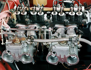
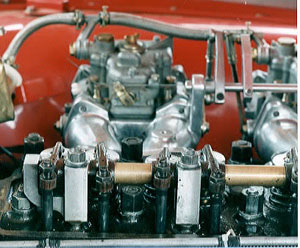
Below are pictures of my TR3A's engine when I was first setting it up. I'm currently running regular fuel lines instead of the stainless braided ones that do not compress under a hose clamp. I also have added a fuel pressure regulator and pressure gauge to the bulkhead above the fuel pump and now route fuel to the carbs around the back side in front of the battery. Otherwise everything is pretty much as you see it. Well with the valve cover off anyway.
Links
Pierce Manifolds The largest source for DCOE parts in the United States. They carry the best sync meter I have found. TWM has sold their carb intake manifold business to Pierce.
Coast Fabrication North American importer of itg race air filters. I assume they also carry itg air horns as well.
6 cyl TR engine application Shane Ingate demystifies triple DCOE set ups for the TR6, GT6 & TR250.
© 1997 - 2017 TeriAnn Wakeman. All rights reserved.